Showing posts with label Scheme. Show all posts

Monday, November 22, 2010

Audio Amplifier LM386 0,325W

The LM386 is a power amplifier designed for use in low voltage consumer applications. The gain is internally set to 20 to keep external part count low, but the addition of an external resistor and capacitor between pins 1 and 8 will increase the gain to any value from 20 to 200.

Audio Amplifier LM386 0,325W SchemaAudio Amplifier LM386 0,325W Shema

The inputs are ground referenced while the output automatically
biases to one-half the supply voltage. The quiescent
power drain is only 24 milliwatts when operating from a 6 volt
supply, making the LM386 ideal for battery operation.

Features
n Battery operation
n Minimum external parts
n Wide supply voltage range: 4V–12V or 5V–18V
n Low quiescent current drain: 4mA
n Voltage gains from 20 to 200
n Ground referenced input
n Self-centering output quiescent voltage
n Low distortion: 0.2% (AV = 20, VS = 6V, RL = 8W, PO =
125mW, f = 1kHz)
n Available in 8 pin MSOP package

Sunday, November 21, 2010

Cut Phone Line Alarm Schema

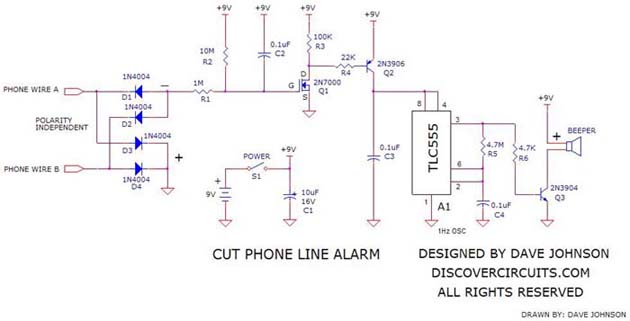
Burglars, rapists and other criminals will often cut a phone line before they break into a home. The cut phone line will prevent many alarm systems from alerting the police. The battery powered circuit below will sound an alarm when the unit no longer detects the voltage present on an active phone line.

Cut Phone Line Alarm SchemaCut Phone Line Alarm Schema

A bridge rectifier front end makes the circuit phone line polarity independent. It shows four 1N4004 diodes being used but you can also use a standard low current bridge rectifier package with a 200v rating or more. The bridge is wired so the output voltage goes negative relative to circuit ground. The phone line will typically be somewhere around 30v when in standby mode and drop to something less than 15v when a phone is connected to the line. In the circuit, this translates a negative voltage fed to the gate of the 2N7000 FET, which kept the transistor turned off. When the phone line is cut, the voltage fed to the gate of the FET will swing to +9v, which will turn on the FET. When Q1 turns on, it also turns on Q2, which routes power to a 555 timer circuit. The 555 timer is wired as a 1Hz square wave oscillator, which drives the transistor Q3. That transistor drives an alarm beeper. With the components shown, the circuit draws nearly zero current in standby mode. Therefore a good quality 9v battery should last for many years.

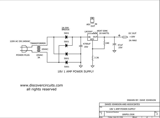
18v AC to DC Power Inventer

This is a classic linear power supply which produces a regulated 18v, rated at about 1 amp.

18v AC to DC Power Inventer

POWER INVENTER 240VAC TO 5VDC

This is simple way to power some 5v logic from a 240vac source. If a 120vac power adapter is used, the circuit will also work for 120vac power lines.

POWER INVENTER 240VAC TO 5VDC Scheme