
Disclaimer
- Each uses the information provided at your own risk.
- I am liable in any way for any damages incurred by the circuits or other information from my side.
- I assume no warranty and no guarantee function for error-free.
- The indicated circuits can only be put into operation by a professional who has the necessary knowledge of electronics and knows the relevant safety regulations.
Description:
- TRXCharger is a small but very powerful charger for nickel-cadmium and nickel-metal hydride batteries. It is designed to charging with high currents after the reflex even single-cell battery load with high efficiency can be. The charge current can be set with a one-button operation in 15 steps (typically 300 mA, 600 mA ... 4500 mA). The end of charging is reliably detected by prediction of the stress maximum. As security is used in addition a "dU" recognition and a timeout. To the formation of new batteries is a normal charge mode (C/10) is implemented with time off.
- Essentially, the circuit from the small ATTiny26 micro controller from Atmel, two power MOSFETs, a 470 uF capacitor and a 100 uH coil. The current control and the charging process are realized by software.
- In fast charge mode is loaded with the set current. To reliably identify the optimal end of charge time, the stream should not be less than C / 2 to be elected (with C is the current in amperes (A) refers to any of the specified nominal battery capacity in ampere-hours (Ah)) represents .
- The charge current when the charge is slowly increased until the nominal current. The summons shall be used in the illustrated cycle:
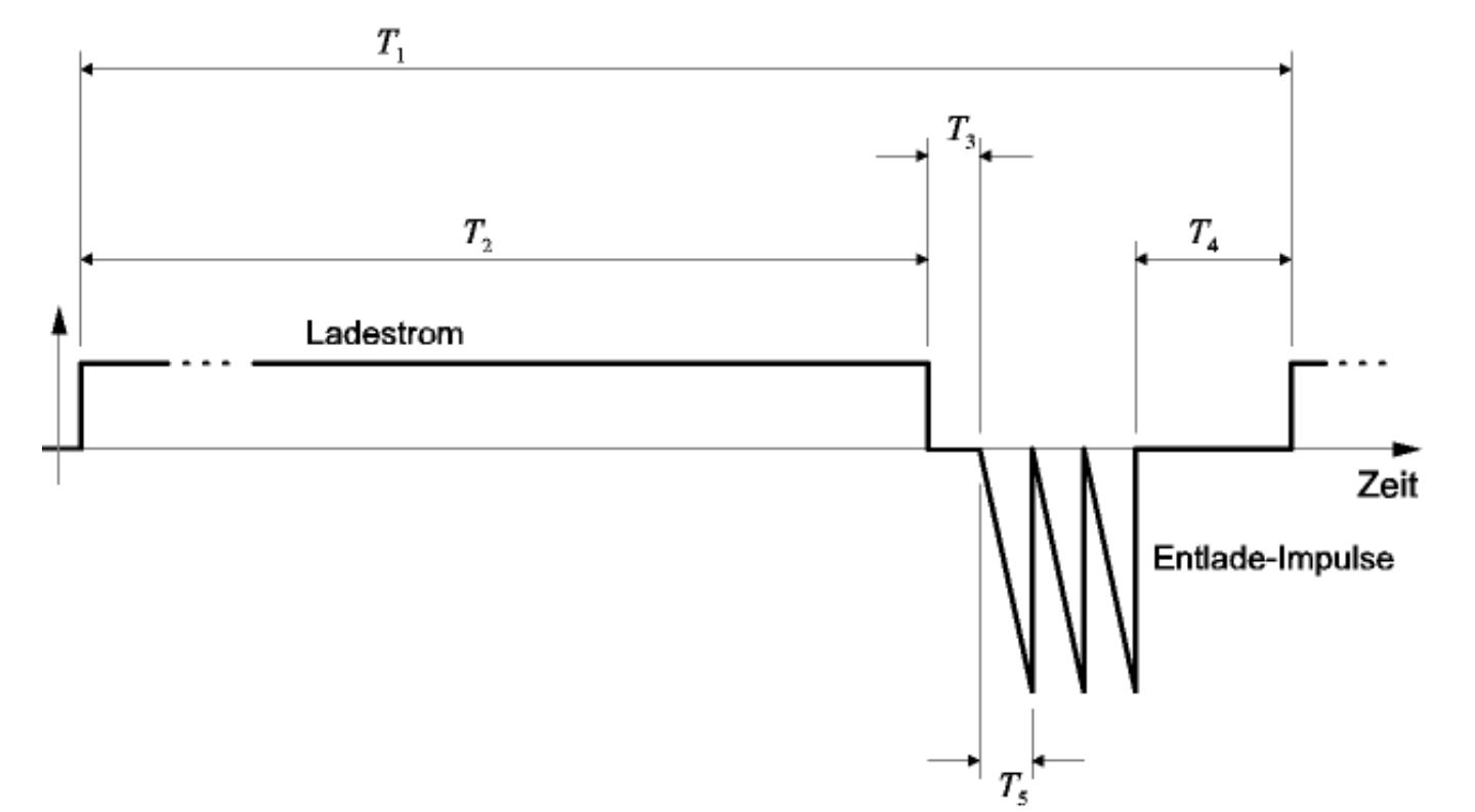
- T_1: Duration of a cycle - about 1:02 s
- T_2: Charging with constant current - about 1 s
- T_3: pause between loading and unloading - about 1 ms
- T_4: Pause for measuring the battery voltage and for example Communication with the computer - about 10 ms
- T_5: duration of a discharge pulse ramp, depending on the maximum discharge current, battery voltage and inductor used - typically 200 us
In the current firmware of the battery with three successive discharge pulses with four times the charge current is applied as a peak.
ReFlex Charger Features:
- Charge current up to about 6 A
- Simple and small structure (single sided: 75x50 mm) and no active cooling, and no heatsink required
- Reflex Laden; triple charge termination: peak prediction,-dU, max. 3h
- Soft start in the fast charge mode
- Normal charge (Closing time is 14 hours)
- One-button operation
- 30 different selectable charge currents (15 and 15 Schnellladeströme Normalladeströme)
- Monitoring of voltage / current and stop criterion possible via serial interface
- Test modes for calibration
ReFlex Charger Technical data:
- Operating voltage: 9 V .. 15 V
- Charging current: 0 .. 6 A
- Charging voltage: 0.5 V .. 8 V (at 12 V operating voltage, up to 4 cell NiCd / NiMH cells, 5)
The voltage source must be able to deliver enough power for the respective charge. With a 12 V / 1 A (= 12 W) power supply, for example, a single battery cell at generously estimated charging voltage of 2 V with a maximum of 6 A load. When two cells are then on the other hand, only 3 A possible.
Images:
Voltage profile during charging of a AA nickel-cadmium cell of Panasonic 1000 mAh nominal capacity. was measured with the internal 10 bit AD converter on the internal reference voltage of about 2:56 V. The measured value was determined by averaging from 32 AD implementations. Clearly, the quantization of the AD converter can be identified.

Voltage profile during charging of a AA nickel-metal hydride cell of Sanyo 2300 mAh nominal capacity:

Schematic and Layout: (Click to more Large)
To use the replica circuits / parts list / layouts from the current project folder, as showing the pictures shown here may be older.
References and improvement are grateful to be included and provide feedback on the successful reproduction would be very happy of course.


Part LIst :


Important information on reproduction and commissioning:
- All the conductors who lead the charge current should be increased by an additional copper wire (see picture).

- The coil must not be used at the adjusted maximum charge / discharge current in the saturation.
- The shunt resistor must be sized so as to fall at the maximum possible charge current maximum of 0125 V. For example, 4 x 15 mm resistance wire with 5 Ohm / m -> maximum charging current = 6.7 A.
- After the first full mounting should Test-/Kalibrierungs-Firmware partly filled and the fuse bits - are set as described in the documentation -.
- After setting up the normal firmware must be programmed two constants in the EEPROM (see instructions):
- I_charge_factor determined (the charge current levels), depending on the shunt resistor
- T_discharge_factor determined (the reflex-discharge), depending on the coil inductance and the voltage divider R13, R14.
- The correct determination of these two constants is described in the instructions. As long as the constants are not yet programmed, the charger after power is immediately change to the error state (all LED flashing fast).
- The supply voltage must be able to provide the average charging power available during the operation and must not fall below the minimum operating voltage, otherwise the P-MOSFET can not be connected properly and will destroy this may cause.
- At a charging current of about 2 amps, the MOSFETs are "lukewarm". If a MOSFET are very hot, there is a fault in the construction.
Download: (schematics, firmware, instructions and sample programs for PC Communications)
Current Version:
trxcharger_0.1.4c_all.zip


